


RF Connector Dimensions
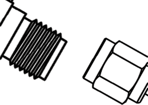
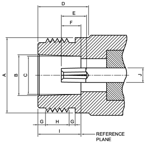
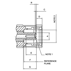
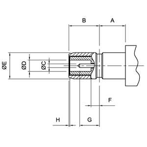
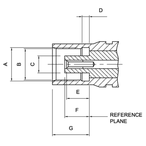
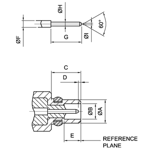
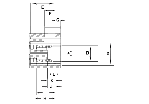
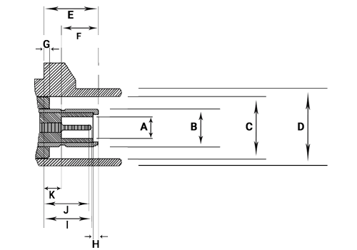
SMA Connector Dimensions
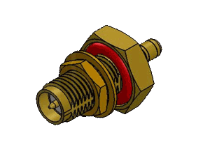
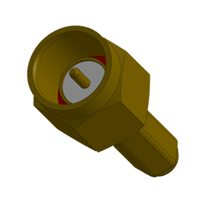
SMA connectors feature screw-type coupling. Semi-Rigid cabling extends their frequency range to 18GHz. SMA connectors offer broadband performance with low reflections and constant 50 ohm impedance. These properties, along with their minimum attenuation and low VSWR, have made the SMA connector extremely popular in the microwave community. LTI’s SMA connectors are designed to conform to MIL-C-39012 specifications.
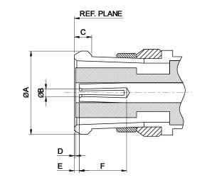
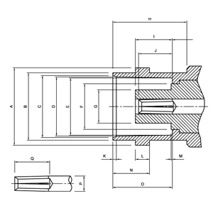
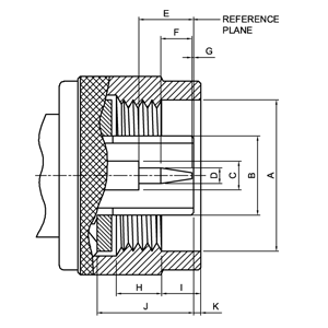
SMA Plug Connector |
SMA Jack Connector |
|||||||||||||||||||||||||||||||||||||||||||||||||||||||||||||||
|---|---|---|---|---|---|---|---|---|---|---|---|---|---|---|---|---|---|---|---|---|---|---|---|---|---|---|---|---|---|---|---|---|---|---|---|---|---|---|---|---|---|---|---|---|---|---|---|---|---|---|---|---|---|---|---|---|---|---|---|---|---|---|---|---|

|

|
|||||||||||||||||||||||||||||||||||||||||||||||||||||||||||||||
|
|
SMA Electrical Ratings
| Impedance | 50 Ω | |||||||||||
|---|---|---|---|---|---|---|---|---|---|---|---|---|
| RF Leakage | -90 dB @ 2-3 GHz | |||||||||||
| Insulation Resistance | 5000 MΩ min | |||||||||||
| Contact Resistance | Center Contact | Outer Contact | ||||||||||
| 3.0 mΩ max | 2.0 mΩ max | |||||||||||
| Straight Connectors | Right Angle Connectors | |||||||||||
| Insertion Loss | .04 dB max x W f GHz | .06 dB max x W f GHz | ||||||||||
| Cable Type | Semi-Rigid | Flexible | Semi-Rigid | Flexible | ||||||||
| Frequency | DC to 18 GHz | DC to 12.4 GHz | DC to 18 GHz | DC to 12.4 GHz | ||||||||
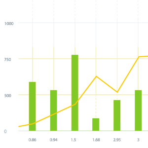
| Cable Dielectric Diameter (mm) | 0.94 | 1.68 | 3 | 0.86 | 1.5 | 2.95 | 0.94 | 1.68 | 3 | 0.86 | 1.5 | 2.95 |
| Dielectric Withstanding Voltage (at sea level, in V rms,50Hz) | 1000 | 1000 | 1500 | 500 | 750 | 1000 | 1000 | 1000 | 1500 | 500 | 750 | 1000 |
| Working Voltage (at sea level, in V rms,50Hz) | 250 | 335 | 500 | 250 | 250 | 335 | 250 | 335 | 500 | 250 | 250 | 335 |
| Corona Extinction Voltage (at 21000m, in V rms,50Hz) | 250 | 250 | 375 | 190 | 190 | 250 | 250 | 250 | 375 | 190 | 190 | 250 |
SMA Mechanical Ratings
| Mating | 1/4"-36 threaded coupling | |
|---|---|---|
| Brass | Stainless Steel | |
| Durability | 100 matings max | 500 matings max |
| Coupling Proof Torque | 5.3 in-lbs | 15 in-lbs |
| Coupling Nut Retention Force | 60.7 lbs min | 60.7 lbs min |
| Contact Captivation - Axial | 6.1 lbs min | 6.1 lbs min |
| Cable Retention | RG 174, 188, 316 | RG 178, 196 |
| 12.1 lbs min | 7.3 lbs min |
SMA Environmental Ratings
| Temperature Range | -65C to +165C |
|---|---|
| Thermal Shock | MIL-STD-202, Method 1017, Condition A |
| Vibration | MIL-STD-202, Method 204, Condition D |
| Corrosion | MIL-STD-202, Method 101, Condition B |
| Temperature Cycling | MIL-STD-202, Method 102, Condition C |
Materials
| Gender | Material | Plating | |
|---|---|---|---|
| Connector Body | Brass per QQ-B-626 | Gold/Nickel | |
| Center Contact | Male | Brass per QQ-B-626 | Gold |
| Female | Beryllium Copper per QQ-C-530 | Gold | |
| Insulator | Teflon | None | |
| Gasket | Silicone Rubber | None | |
| Crimp Ferrule | Annealed Copper per WW-T-799 | Same as body |
SMP Connector Dimensions
The SMP has a subminiature interface suitable for miniaturized high frequency coaxial modules up to 40Ghz. SMPs can be used as PC board to board interconnects by connecting a Plug SMP to each of the PC boards using a Jack-to-Jack adapter.
SMP Jack Cabled Connector |
SMP Jack Dimensions |
|||||||||||||||||
|---|---|---|---|---|---|---|---|---|---|---|---|---|---|---|---|---|---|---|
|
|
SMP Electrical Ratings
| Impedance | 50 Ω |
|---|---|
| RF Leakage | -80db mini. at 3GHz; -65dB mini. from 3 to 26.5 GHz |
| Insulation Resistance | >= 5000M Ω |
| Contact Resistance Inner Conductor | <= 6m Ω |
| Contact Resistance Outer Conductor | <= 2m Ω |
| Frequency | DC up to 40 GHz |
| Dielectric Withstanding Voltage (at sea level, in V rms, 50Hz) | >500 |
| Working Voltage (at sea level, in V rms, 50Hz) | 335 |
SMP Mechanical Ratings
| Mecganical Data | Full Detent | Limited Detent | Smooth Bore & Catcher Mit |
|---|---|---|---|
| Durability (matings) | 100 (min) | 500 (min) | 5000 (min) |
| Misalignment | +/- 0.508(.020) Radial, +0.000/-0.254(+.000/-.010) Axial | ||
| Force to Engage (lbs.max) | 15.0 | 5.0 | 2.0 |
| Force to DisEngage (lbs.max) | 5.0 | 1.5 | 0.5 |
SMP Environmental Ratings
| Moisture Resistance | MIL-STD-202, Method 106 |
|---|---|
| Corrosion | MIL-STD-202, Method 101, Condition B |
Materials
| Parts | Material | Plating |
|---|---|---|
| Cover | Brass | Gold 4 Over Nickel-Phosphorus Alloy 80 Over Copper 20 |
| Renber Ring | Beryllium Copper | Gold 4 Over Nickel-Phosphorus Alloy 80 Over Copper 20 |
| Contact Pin | Beryllium Copper | Gold 4 Over Nickel-Phosphorus Alloy 80 Over Copper 20 |
| Insulator | Teflon | |
| Body | Beryllium Copper | Gold 4 Over Nickel-Phosphorus Alloy 80 Over Copper 20 |
I-PEX MHF Connector Dimensions
The micro-miniature IPX connector from Lighthorse Technologies, Inc. is ideal for a variety of space-critical wireless applications such as IEEE802.11a/b/g/n, UWB, WIMAX, Bluetooth, iBurst, ZigBee, and MIMO. Operating up to 6GHz, the low-profile (2.5mm) IPX connector has a 3mm square PCB footprint. The IPX connector is 100% compatible with all Hirose U.FL interfaces. Cable Crimp IPX connectors can be attached to Coaxial cables such as RG-178, 1.13mm micro coax, and 1.32mm double shielded cables cut to any length.
I-PEX MHF R/A Jack (P/N LTI-IPXLF11GBP-XX) |
I-PEX MHF Surface Mount Plug (P/N LTI-IPXSM66AL) |
|||||||||||||||||||||||||||
|---|---|---|---|---|---|---|---|---|---|---|---|---|---|---|---|---|---|---|---|---|---|---|---|---|---|---|---|---|

|

|
|||||||||||||||||||||||||||
|
|
|||||||||||||||||||||||||||
I-PEX MHF Electrical Ratings
| Impedance | 50 Ω | |||||
|---|---|---|---|---|---|---|
| Insulation Resistance | >= 500M Ω | |||||
| Contact Resistance | Center Contact | Outer Contact | ||||
| 20 m ohms max. | 10 m ohms max. | |||||
| Rated Voltage | AC 60V | |||||
| Withstand Voltage | AC 200V | |||||
| Frequency | Up to 3gHz | 3gHz to 6gHz | ||||
| V.S.W.R. | 1.3 Max | 1.4 Max | ||||
| Coax Cable | 1.13mm | 1.32mm | RG-178 | 5.44dB/m | 5.6dB/m | 4.9dB/m |
I-PEX MHF Materials
| Parts | Material | Plating/Color | Note |
|---|---|---|---|
| Housing | PBT UL94V-0 | Natural or Black | Only Au 08, Au 18 is NATURAL |
| Contact | Copper Alloy | Au | |
| Ground Contact | Copper Alloy | Au or Ag |
BNC Connector Dimensions
BNC connectors are the most popular coaxial connector. Their bayonet design allows for easy mating and unmating. BNC 50 ohm connectors provide repeatable electronic performance from DC to 4 GHz. BNC 75 ohm connectors are suitable for applications up to 1 GHz. All 50 and 75 ohm connectors are intermatable. BNC connectors are designed to accomodate a large variety of RG and industry standard cables. They are available in crimp, clamp, and twist on cable styles. A full line of printed circuit board receptacles, bulkhead receptacles, and other accessories complement the product offering. LTI’s BNC connectors are designed to conform to MIL-C-39012 specifications. The BNC series coaxial connector works well in lower microwave frequency applications including monitors, LAN, telecommunication devices, and test equipment.
BNC Plug Connector |
BNC Jack Connector |
||||||||||||||||||||||||||||||||||||||||||||||||||||||||||||||||||||||||||||||||||||||||||
|---|---|---|---|---|---|---|---|---|---|---|---|---|---|---|---|---|---|---|---|---|---|---|---|---|---|---|---|---|---|---|---|---|---|---|---|---|---|---|---|---|---|---|---|---|---|---|---|---|---|---|---|---|---|---|---|---|---|---|---|---|---|---|---|---|---|---|---|---|---|---|---|---|---|---|---|---|---|---|---|---|---|---|---|---|---|---|---|---|---|---|---|

|
|
||||||||||||||||||||||||||||||||||||||||||||||||||||||||||||||||||||||||||||||||||||||||||
|
|
||||||||||||||||||||||||||||||||||||||||||||||||||||||||||||||||||||||||||||||||||||||||||
BNC Electrical Ratings
| Impedance | 50 Ω | 75 Ω |
|---|---|---|
| Frequency Range | DC to 4 GHz | DC to 1 GHz |
| VSWR | Straight | Right Angle |
| 1.3 max | 1.35 max | |
| Working Voltage (at sea level, in R rms,50Hz) | 500 | |
| Dielectric Withstanding Voltage (at sea level, in V rms,50Hz) | 1500 | |
| Insulation Resistance | 5000 MΩ min | |
| Insertion Loss | 0.2 dB max @ 3.0 GHz | |
| Contact Resistance | Center Contact | Outer Contact |
| 2.0 mΩ max | 2.0 mΩ max | |
BNC Mechanical Ratings
| Mating | Bayonet style snap-on coupling | |
|---|---|---|
| Durability | 500 matings max | |
| Coupling Nut Torque | 0.6 to 2.5 in-lbs | |
| Coupling Nut Retention Force | 101.2 lbs max | |
| Contact Captivation | 6.1 lbs max | |
| Cable Retention | RG 174, 188, 316 | RG 58,59 |
| 12.1 lbs min | 28.7 lbs min | |
BNC Environmental Ratings
| Temperature Range | -65C to +165C |
|---|---|
| Thermal Shock | MIL-STD-202F, Method 1017G, Condition A |
| Vibration | MIL-STD-202F, Method 204D, Condition A |
| Corrosion | MIL-STD-202F, Method 101D, Condition B |
| Mechanical Shock | MIL-STD-202F, Method 213B, Condition A |
BNC Materials
| Gender | Material | Plating | |
|---|---|---|---|
| Connector Body | Brass per QQ-B-626 | Nickel | |
| Center Contact | Male | Brass per QQ-B-626 | Gold |
| Female | Beryllium Copper per QQ-C-530 | Gold | |
| Insulator | Teflon, Delrin, Polypropylene | None | |
| Gasket | Silicone Rubber | None | |
| Crimp Ferrule | Annealed Copper per WW-T-799 | Same as body |
TNC Connector Dimensions
TNC RF connectors are essentially BNC connectors with threaded coupling and improved electrical performance at higher frequencies. TNC 50 ohm connectors provide repeatable electronic performance from DC to 11 GHz. TNC 75 ohm connectors are suitable for applications up to 1 GHz. All 50 and 75 ohm connectors are intermatable. TNC connectors are designed to accommodate cables from .150" to .250” OD. The TNC type connector is a weatherproof unit and with its threaded coupling ensures low noise. It can also withstand shock and vibration. LTI TNC connectors are designed to conform to MIL-C-39012 specifications. Typical TNC series coaxial connector applications include the airframe, missile, radar, cellular mobile phone, and precision electronic equipment industries.
TNC Plug Connector |
TNC Jack Connector |
|||||||||||||||||||||||||||||||||||||||||||||||||||||||||||||||||||||||||||||||||||||||||||||
|---|---|---|---|---|---|---|---|---|---|---|---|---|---|---|---|---|---|---|---|---|---|---|---|---|---|---|---|---|---|---|---|---|---|---|---|---|---|---|---|---|---|---|---|---|---|---|---|---|---|---|---|---|---|---|---|---|---|---|---|---|---|---|---|---|---|---|---|---|---|---|---|---|---|---|---|---|---|---|---|---|---|---|---|---|---|---|---|---|---|---|---|---|---|---|

|

|
|||||||||||||||||||||||||||||||||||||||||||||||||||||||||||||||||||||||||||||||||||||||||||||
|
|
TNC Electrical Ratings
| Impedance | 50 Ω | 75 Ω |
|---|---|---|
| Frequency Range | DC-11 GHz | DC-1 GHz |
| VSWR | 1.3 max | |
| Voltage Rating (in VRMS at sea level) | 500 max | |
| Dielectric Withstanding Voltage (in VRMS at sea level) | 1500 min | |
| Insulation Resistance | 5000 MΩ min | |
| Insertion Loss | 0.2 dB max @ 3.0 GHz | |
| Contact Resistance | Center Contact | Outer Contact |
| 2.0 mΩ max | 1.0 mΩ max | |
TNC Mechanical Ratings
| Mating | 7/16" threaded coupling coupling | |
|---|---|---|
| Durability | 500 matings max | |
| Coupling Nut Torque | 4/1 to 6.1 in-lbs | |
| Coupling Nut Retention Force | 101.2 lbs max | |
| Contact Captivation | 6.1 lbs max | |
| Cable Retention | Semi-Rigid and Clamp Type | 40 lbs min |
| RG-178,196 | 7.3 lbs min | |
| RG-174,188,316 | 12.1 lbs min | |
| RG-58,59 | 28.7 lbs min | |
TNC Environmental Ratings
| Temperature Range | -65C to +165C |
|---|---|
| Thermal Shock | MIL-STD-202F, Method 1017G, Condition A |
| Vibration | MIL-STD-202F, Method 204D, Condition A |
| Corrosion | MIL-STD-202F, Method 101D, Condition B |
| Mechanical Shock | MIL-STD-202F, Method 213B, Condition A |
BNC Materials
| Gender | Material | Plating | |
|---|---|---|---|
| Connector Body | Brass per QQ-B-626 | Nickel | |
| Center Contact | Male | Brass per QQ-B-626 | Gold |
| Female | Beryllium Copper per QQ-C-530 | Gold | |
| Insulator | Teflon, Delrin, Polypropylene | None | |
| Gasket | Silicone Rubber | None | |
| Crimp Ferrule | Annealed Copper per WW-T-799 | Same as body |
N Connector Dimensions
N series RF connectors are 50 ohm constant impedance connectors with a consistently low VSWR across their frequency range of DC to 11GHz. They are high-quality medium sized connectors that are generally used with coaxial cables from .350" to .450" OD, but designs can also accommodate .078" to .875" cables. N type connectors are threaded and gasketed for weatherproof operation.
The threaded coupling incurs low noise and withstands shock and vibration. LTI’s N connectors are designed to conform to MIL-C-39012 specifications. Lighthorse Technologies offers a few 75 ohm impedance versions of N connectors. However; they are not mateable with the 50 ohm connectors. The N series connector is the most popular medium sized connector. Common applications utilizing N connectors include test and measurement systems, antennae, base stations, and transmitters.
N Plug Connector |
N Jack Connector |
|||||||||||||||||||||||||||||||||||||||||||||||||||||||||||||||||||||
|---|---|---|---|---|---|---|---|---|---|---|---|---|---|---|---|---|---|---|---|---|---|---|---|---|---|---|---|---|---|---|---|---|---|---|---|---|---|---|---|---|---|---|---|---|---|---|---|---|---|---|---|---|---|---|---|---|---|---|---|---|---|---|---|---|---|---|---|---|---|---|
|
|
|||||||||||||||||||||||||||||||||||||||||||||||||||||||||||||||||||||
|
|
Type-N Electrical Ratings
| Impedance | 50 Ω | 75 Ω |
|---|---|---|
| Frequency Range | DC-11 GHz | DC-1.5 GHz |
| VSWR | 1.3 max @ 11 GHz | |
| Voltage Rating (in VRMS at sea level) | 1000 max | |
| Dielectric Withstanding Voltage (in VRMS at sea level) | 2500 min | |
| Insertion Loss | .15 dB max @ 10 GHz | |
| Insulation Resistance | 5000 MΩ min | |
| Contact Resistance | Center Contact | Outer Contact |
| 1.0 mΩ max | 1.0 mΩ max | |
Type-N Mechanical Ratings
| Mating | 5/8-24UNEF threaded coupling | |
|---|---|---|
| Durability | 500 matings max | |
| Coupling Nut Torque | 6 to 10 in-lbs | |
| Coupling Proof Torque | 15 in-lbs | |
| Coupling Nut Retention Force | 101.2 lbs max | |
| Contact Captivation | 6.1 lbs max | |
| Cable Retention | RG-174,188,316 | 20 lbs min |
| RG-58,142,223,400 | 40 lbs min | |
| RG-59,62,210 | 40 lbs min | |
| RG-8,11,213,214 | 80 lbs min | |
Type-N Environmental Ratings
| Temperature Range | -65C to +165C |
|---|---|
| Thermal Shock | MIL-STD-202, Method 1017G, Condition A |
| Vibration | MIL-STD-202, Method 204D, Condition A |
| Corrosion | MIL-STD-202, Method 101D, Condition B |
| Mechanical Shock | MIL-STD-202, Method 213B, Condition A |
Type-N Materials
| Gender | Material | Plating | |
|---|---|---|---|
| Connector Body | Brass per QQ-B-626 | Nickel | |
| Center Contact | Male | Brass per QQ-B-626 | Gold |
| Female | Beryllium Copper per QQ-C-530 | Gold | |
| Insulator | Teflon, Delrin, Polypropylene | None | |
| Gasket | Silicone Rubber | None | |
| Crimp Ferrule | Annealed Copper per WW-T-799 | Same as body |
SMB Connector Dimensions
SMB RF connectors are semi-precision subminiature devices that provide repeatable electrical performance from DC to 4 GHz. The SMB family of connectors provides a means of quick connect and disconnect through a snap-on type coupling, making them useful in areas that are inaccessible to normal mating action.
Its smaller physical size and snap-on coupling make the SMB an ideal general purpose connector where packaging density, ease of mating/unmating, and economy are prerequisites. Typical applications for SMB connectors are telecommunications, test equipment, instrumentation, and GPS. They are best suited for use with cables in the range of .070" to .120" in diameter, such as RG 178, RG 174, RG 316. The series is similar in size to the SMC connector but is generally used at a lower frequency. LTI’s SMB type connectors are designed to conform to MIL-C-39012 specifications.
SMB Plug Connector |
SMB Jack Connector |
|||||||||||||||||||||||||||||||||||||||||||||||||||||||||||||||
|---|---|---|---|---|---|---|---|---|---|---|---|---|---|---|---|---|---|---|---|---|---|---|---|---|---|---|---|---|---|---|---|---|---|---|---|---|---|---|---|---|---|---|---|---|---|---|---|---|---|---|---|---|---|---|---|---|---|---|---|---|---|---|---|---|
|

|
|||||||||||||||||||||||||||||||||||||||||||||||||||||||||||||||
|
|
SMB Electrical Ratings
| Impedance | 50 Ω | |
|---|---|---|
| Frequency Range | DC to 4 GHz | |
| RG-174,188,316 | RG-178,196 | |
| Dielectric Withstanding Voltage (at sea level, in V rms, 50 Hz) | 1000 | 750 |
| Working Voltage (at sea level, in V rms, 50 Hz) | 335 max | 250 max |
| Insulation Resistance | 1000 MΩ min | |
| RF Leakage | -55dB max @ 2.5 GHz | |
| Insertion Loss | Straight | Right Angle |
| .3dB max @ 1.5 GHz | .6dB max @ 1.5 GHz | |
| Contact Resistance | Center Contact | Outer Contact |
| 5 mΩ max | 1 mΩ max | |
SMB Mechanical Ratings
| Mating | Snap-on Coupling | |
|---|---|---|
| Durability | 500 matings max | |
| Coupling Nut Retention Force | 36 lbs min | |
| Contact Captivation | 4 lbs min | |
| Cable Retention | RG 174,188,316 | RG 178,196 |
| 20 lbs min | 6 lbs min | |
SMB Environmental Ratingss
| Temperature Range | -65C to +165C |
|---|---|
| Thermal Shock | MIL-STD-202, Method 1017, Condition A |
| Vibration | MIL-STD-202, Method 204, Condition D |
| Corrosion | MIL-STD-202, Method 101, Condition B |
| Temperature Cycling | MIL-STD-1344, Method 1003, Condition A |
SMB Materials
| Gender | Material | Plating | |
|---|---|---|---|
| Connector Body | Brass per QQ-B-626 | Gold/Nickel | |
| Center Contact | Male | Brass per QQ-B-626 | Gold |
| Female | Beryllium Copper per QQ-C-530 | Gold | |
| Insulator | Teflon | None | |
| Gasket | Silicone Rubber | None | |
| Crimp Ferrule | Annealed Copper per WW-T-799 | Same as body |
SSMB Connector Dimensions
SSMB RF connectors are microminiature devices that provide repeatable electrical performance from DC to 3GHz. The standard mating design for SSMB series connectors is similar to that of SMB and SMC connectors but with the size reduced by approximately one-third. This makes them ideal for use in confined areas where the use of wrenches is not practical. They are lightweight, easy to connect and disconnect, vibration-proof, and highly reliable.
They are best suited for use with cables in the range of .070" to .120" diameters, such as RG-178, RG-174, and RG-316. Because of their small-size and tight tolerance, finishes other than gold plating are not recommended. SSMB type connectors have gained wide acceptance and usage in military radio systems, where small size is needed for miniaturization but ruggedness and reliability are very important.
SSMB Plug Connector |
SSMB Jack Connector |
|||||||||||||||||||||||||||||||||||||||||||||||||||
|---|---|---|---|---|---|---|---|---|---|---|---|---|---|---|---|---|---|---|---|---|---|---|---|---|---|---|---|---|---|---|---|---|---|---|---|---|---|---|---|---|---|---|---|---|---|---|---|---|---|---|---|---|

|
|
|||||||||||||||||||||||||||||||||||||||||||||||||||
|
|
SSMB Electrical Ratings
| Impedance | 50 Ω | |
|---|---|---|
| Frequency Range | DC to 3 GHz | |
| Dielectric Withstanding Voltage (at sea level, in V rms, 50 Hz) | 500 max | |
| Working Voltage(at sea level, in V rms, 50 Hz) | 250 max | |
| Insulation Resistance | 1000 MΩ min | |
| RF Leakage | -70 dB min @ 2-3 GHz | |
| VSWR | Straight | Right Angle |
| 1.22 max @ 0-1.0 GHz | 1.50 max @ 0-1.0 GHz | |
| 1.35 max @ 0-3.0 GHz | 1.63 max @ 0-3.0 GHz | |
| Contact Resistance | Center Contact | Outer Contact |
| 5 mΩ max | 2.5 mΩ max | |
SSMB Mechanical Ratings
| Mating | Snap-on coupling |
|---|---|
| Durability | 500 matings max |
| Engagement/Disengagement Force | 6 lbs max engagement/1 lb min disengagement |
| Contact Captivation | 2 lbs min axial force |
| Temperature Range | -55C to +155C |
SSMB Materials
| Gender | Material | Plating | |
|---|---|---|---|
| Connector Body | Brass per QQ-B-626 | Gold/Nickel | |
| Center Contact | Male | Brass per QQ-B-626 | Gold |
| Female | Beryllium Copper per QQ-C-530 | Gold | |
| Insulator | Teflon | None | |
| Gasket | Silicone Rubber | None | |
| Crimp Ferrule | Annealed Copper per WW-T-799 | Same as body |
MCX Connector Dimensions
MCX microminature RF connectors are suitable for 50 ohm applications and provide repeatable performance from DC to 6GHz. Their snap-on coupling feature allows ease of assembly in dense packaging layouts. The design of the connector encompasses the need for size reduction, low weight, durability, and reliable performance. MCX type connectors enable a 30% space reduction over similar SMB/SMC types. LTI’s MCX connectors are designed to conform to CECC 22220 specifications. MCX connectors are typically used in GPS, wireless communications, and automotive applications.
MCX Plug Connector |
MCX Jack Connector |
||||||||||||||||||||||||||||||||||||||||||||||||
|---|---|---|---|---|---|---|---|---|---|---|---|---|---|---|---|---|---|---|---|---|---|---|---|---|---|---|---|---|---|---|---|---|---|---|---|---|---|---|---|---|---|---|---|---|---|---|---|---|---|

|
|
||||||||||||||||||||||||||||||||||||||||||||||||
|
|
MCX Electrical Ratings
| Impedance | 50 Ω | ||
|---|---|---|---|
| Frequency Range | DC to 3 GHz | ||
| Cable Type | Straight | Right Angle | |
| Dielectric Withstanding Voltage (at sea level, in V rms, 50 Hz) | RG 174,188,316,.086" | 750 min | 1000 min |
| Working Voltage(at sea level, in V rms, 50 Hz) | RG 178,196,.047" | 250 max | 335 max |
| Insulation Resistance | 10,000 MΩ min | ||
| Insertion Loss | .1dB max @ 1.0 GHz | ||
| Contact Resistance | Center Contact | Outer Contact | |
| 5 mΩ max | 1 mΩ max | ||
MCX Mechanical Ratings
| Mating | Snap-on coupling | |
|---|---|---|
| Durability | 500 matings | |
| Engagement Force | 5.6 lbs max | |
| DisEngagement Force | 1.8 lbs to 4.5 lbs | |
| Contact Captivation | 4.5 lbs. min | |
| Cable Retention | RG 174, 188, 316 | RG 178, 196 |
| 12.1 lbs min | 7.3 lbs min | |
MCX Environmental Ratings
| Temperature Range | -65C to +165C |
|---|---|
| Vibration | MIL-STD-202, Method 204, Condition B |
| Corrosion | MIL-STD-202, Method 101, Condition B |
| Temperature Cycling | MIL-STD-1344, Method 1003, Condition A |
MCX Materials
| Gender | Material | Plating | |
|---|---|---|---|
| Connector Body | Brass per QQ-B-626 | Gold/Nickel | |
| Center Contact | Male | Brass per QQ-B-626 | Gold |
| Female | Beryllium Copper per QQ-C-530 | Gold | |
| Insulator | Teflon | None | |
| Crimp Ferrule | Annealed Copper per WW-T-799 | Same as body |
MMCX Connector Dimensions
MMCX micro-miniature RF connectors are suitable for 50 ohm applications and provide repeatable electronic performance from DC to 6 GHz. The snap-on mating design offers low RF leakage and ease of assembly in dense packaging layouts. The MMCX series is one of the smallest connectors that Lighthorse Technologies, Inc. currently offers, allowing for usage in space critical applications. MMCX type connectors are lightweight, compact, and reliable. Typical applications for MMCX connectors are PCMCIA cards and other small hand-held communications devices.
MMCX Plug Connector |
MMCX Jack Connector |
|||||||||||||||||||||||||||||||||||||||||||||||||||||||||
|---|---|---|---|---|---|---|---|---|---|---|---|---|---|---|---|---|---|---|---|---|---|---|---|---|---|---|---|---|---|---|---|---|---|---|---|---|---|---|---|---|---|---|---|---|---|---|---|---|---|---|---|---|---|---|---|---|---|---|

|
|
|||||||||||||||||||||||||||||||||||||||||||||||||||||||||
|
|
|||||||||||||||||||||||||||||||||||||||||||||||||||||||||
MMCX Electrical Ratings
| Impedance | 50 Ω | ||
|---|---|---|---|
| Frequency Range | 0-6 GHz | ||
| VSWR | Cable Type | Straight | Right Angle |
| RG 174,188,316 | 1.20 max | 1.25 max | |
| RG 178,196 | 1.20 max | 1.25 max | |
| Voltage Rating(min) | 170 VRMS at sea level | ||
| Dielectric Withstanding Voltage | 500 VRMS minimum | ||
| Contact Resistance | Center Contact | Outer Contact | |
| 10.0 mΩ max | 5.0 mΩ max | ||
MMCX Mechanical Ratings
| Mating | Snap-on coupling | |
|---|---|---|
| Durability | 500 matings | |
| Engagement Force | 8 lbs max | |
| DisEngagement Force | 1.4 lbs min | |
| Cable Retention | RG 174, 188, 316 | RG 178, 196 |
| 12.1 lbs min | 7.3 lbs min | |
MMCX Environmental Ratings
| Temperature Range | -65C to +165C |
|---|---|
| Thermal Shock | MIL-STD-202F, Method 1017G, Condition A |
| Vibration | MIL-STD-202F, Method 204D, Condition A |
| Corrosion | MIL-STD-202F, Method 101D, Condition A |
| Mechanical Shock | MIL-STD-202F, Method 213B, Condition A |
MMCX Materials
| Gender | Material | Plating | |
|---|---|---|---|
| Connector Body | Brass per QQ-B-626 | Gold/Nickel | |
| Center Contact | Male | Brass per QQ-B-626 | Gold |
| Female | Beryllium Copper per QQ-C-530 | Gold | |
| Insulator | Teflon | None | |
| Crimp Ferrule | Annealed Copper per WW-T-799 | Same as body |
FAKRA Connector Dimensions
The FAKRA line was designed in response to new interface standards created by the automotive industry. The FAKRA: ISO 20860-1/DIN72594-1 and USCAR: SAE 2, 17, 18 standards designate several essential characteristics of FAKRA/USCAR connectors, including: RF electrical performance identical to an SMB coaxial connector, a plastic housing featuring mechanical and color coding (each color referring to a specific application), and high mechanical performance that meets the requirements of the automotive industry. Both FAKRA and USCAR compliant connectors are based on the coaxial SMB interface and are fully intermateable.
Fakra Jack Connector |
Fakra Plug Connector |
||||||||||||||||||||||||||||||||||||||||||||||||||||||||||||||||||||||||
|---|---|---|---|---|---|---|---|---|---|---|---|---|---|---|---|---|---|---|---|---|---|---|---|---|---|---|---|---|---|---|---|---|---|---|---|---|---|---|---|---|---|---|---|---|---|---|---|---|---|---|---|---|---|---|---|---|---|---|---|---|---|---|---|---|---|---|---|---|---|---|---|---|---|
|
|
||||||||||||||||||||||||||||||||||||||||||||||||||||||||||||||||||||||||
|
|
Fakra Electrical Ratings
| Impedance | 50 Ω | |
|---|---|---|
| Frequency Range | DC to 6 GHz | |
| Loss | Return | Insertion |
| 18 dB min | 0.1 x √f(GHz) dB max | |
| Insulation Resistance | 1000 GΩ | |
| Working Voltage Rating(at sea level) | 335 V rms | |
| Dielectric Withstanding Voltage(at sea level) | 1000 min | |
| RF Leakage | 65 dB min | |
| Contact Resistance | Center Contact | Outer Contact |
| 5 mΩ max | .02 5 max | |
Fakra Mechanical Ratings
| Mating | 25 min |
|---|---|
| Durability | 100 matings max |
| Engagement Force | 25 N max |
| DisEngagement Force | 2 min |
| Retention Force | 110 min |
Fakra Environmental Ratings
| Temperature Range | -40°C - +110°C |
|---|---|
| Vibration/Mechanical Shock | ISO 20860-2 clause 9.1 |
| Thermal Shock | ISO 20860-2 clause 9.2 |
| Temperature/Humidity Cycling | ISO 20860-2 clause 9.3 |
| High Temperature Exposure | ISO 20860-2 clause 9.4 |
Fakra Materials
| Material | Plating | |
|---|---|---|
| Connector Body | CuZn, CuSn, Zn, Stainless steel | Au, Ni, Sn |
| Center Contact | CuZn, CuBe, CuSn | Au |
| Dielectric | PTFE, PA, LCP, PBT | Au, Ni, Sn |
| Gasket | Silicone, Rubber | Au, Ni, Sn |
| Crimp Ferrule | Cu | Same as body |
7/16 Connector Dimensions
7/16 series RF connectors are 50 ohm constant impedance connectors with repeatable electrical performance from DC to 7.5 GHz. They are medium-size rugged connectors and feature good power-handling capability. 7/16 connectors are designed to minimize signal distortion from intermodulation. Because of this, the standard plating is silver. Optional nickel plating should only be specified when low intermodulation is not a concern in your system design. At this time, Lighthorse Technologies only offers panel mount versions of the 7/16 as standard connectors. However, if you require a different mounting style, we will be happy to consider your requirements to provide a working solution.
7/16 Jack Cabled Connector |
7/16 Plug Cabled Connector |
||||||||||||||||||||||||||||||||||||||||||||||||||||||||||||
|---|---|---|---|---|---|---|---|---|---|---|---|---|---|---|---|---|---|---|---|---|---|---|---|---|---|---|---|---|---|---|---|---|---|---|---|---|---|---|---|---|---|---|---|---|---|---|---|---|---|---|---|---|---|---|---|---|---|---|---|---|---|

|

|
||||||||||||||||||||||||||||||||||||||||||||||||||||||||||||
|
|
7/16 Electrical Ratings
| Impedance | 50 Ω | |
|---|---|---|
| Frequency Range | 0-7.5 GHz | |
| VSWR | Straight | Right Angle |
| 1.3 max | 1.5 max | |
| Voltage Rating(in VRMS at sea level) | 2700 max | |
| Dielectric Withstanding Voltage (in VRMS at sea level) | 4000 min | |
| Insulation Resistance | 5000 MΩ min | |
| Contact Resistance | Center Contact | Outer Contact |
| 0.4 mΩ max | .02 mΩ max | |
7/16 Mechanical Ratings
| Mating | M29 x 1.5 threaded coupling |
|---|---|
| Durability | 500 matings max |
| Coupling Proof Torque | 310 in-lbs max |
| Coupling Nut Retention Force | 225 lbs max |
| Contact Captivation | 45 lbs min |
7/16 Materials
| Gender | Material | Plating | |
|---|---|---|---|
| Connector Body | Brass per QQ-B-626 | Silver/Nickel | |
| Center Contact | Male | Brass per QQ-B-626 | Gold |
| Female | Phosphor Bronze per QQ-B-750 | Gold | |
| Insulator | Teflon, Delrin, Polypropylene | None | |
| Gasket | Silicone Rubber | None | |
| Crimp Ferrule | Annealed Copper per WW-T-799 | Same as body |